
Technical Introduction to a Urea Plate Heat Exchanger with Dedusting Function
Written By: Zhang Houqing, Wu Zhaoquan
Abstract: This technology is a urea bulk solids plate heat exchanger with the function of removing solid particle dust. It provides both dedusting and cooling functions and is suitable for solid granular product industries that require both cooling and dust removal, such as urea, compound fertilizer, plastics, and other solid granular materials. The urea plate cooler with dedusting function offers advantages including low energy consumption, low operating cost, removal of dust from products, small footprint, and no exhaust gas emissions, making it a green and low-carbon cooling technology.
Keywords: dedusting function; urea plate cooler; dust removal; cooling technology
1. Technical Background
Cooling and dedusting urea granules is an important process for product quality control in urea production. Without cooling, urea granules are prone to high-temperature adhesion and caking. During natural cooling inside packaging bags, high-temperature product can cause moisture migration, reduced particle strength, pulverization, and other problems. Without dedusting, the powder content inside packaging bags often becomes too high, affecting product appearance and exceeding producers’ internal requirements for product dust content. Excessive dust in packaging bags can cause issues during fertilizer application, creating inconvenience and even leading users to complain about product quality. Excessive dust content also increases the surface area of granules, making urea particles more likely to cake. These issues restrict product sales for urea producers and negatively affect enterprise profitability and brand image.
2. Several Typical Cooling Processes and Technical Characteristics Used by Urea Enterprises
(1) Fluidized-bed cooling technology
Early urea producers mainly used fluidized-bed coolers and vibrating fluidized-bed coolers in production. Both are air-cooling technologies that provide cooling and dedusting. A fluidized-bed cooler uses air as the cooling medium; urea particles contact the air in a fluidized state, and cooling occurs through the temperature difference between the air and the particles. Using a fluidized-bed cooler requires a fan to supply fluidizing air. Because the urea particles are fluidized, large amounts of dust are generated during cooling, requiring additional dust recovery equipment, such as cyclone separation or wet scrubbing, and an induced draft fan. In addition, the moisture content of the air will change seasonally and depending on weather conditions. The introduced air can increase the moisture content of urea particles. To produce qualified products under hot and humid summer conditions, air dehumidification equipment is required. Therefore, fluidized-bed cooling technology requires many pieces of equipment, a long process flow, a large footprint, complex operation and maintenance, and high power consumption. As energy prices continue to rise, urea enterprises increasingly emphasize energy saving, emission reduction, cost reduction, and efficiency improvement. The shortcomings of fluidized-bed cooling technology have therefore become increasingly apparent, and urea enterprises urgently need more energy-efficient cooling technologies.
(2) Rotary-drum cooling technology
Some early urea producers also used rotary-drum coolers in production, mainly in large-granule urea processes. Rotary-drum cooling is also an air-cooling technology. Under the suction of an induced draft fan, airflow inside the rotating cylinder is accelerated. Lifting flights installed on the rotating wall continuously lift and tumble the material, allowing the air to contact the material and achieve cooling. The cooling process generates large amounts of dust, requiring dust recovery equipment, such as cyclone separation or wet scrubbing, and an induced draft fan. Because rotary-drum coolers cannot be fully sealed, dust raised during production has a significant impact on the workshop environment. In addition, like fluidized-bed cooling, performance may be impacted by high ambient humidity. The introduced air can increase the moisture content of urea, and air dehumidification equipment is required to produce qualified products under hot and humid summer conditions. The disadvantages of rotary-drum cooling technology—including large footprint, poor site environment, relatively high power consumption, and poor cooling performance—have gradually become evident.
(3) Urea plate cooler
Since the 1980s, urea plate cooler technology has been widely applied in urea enterprises. This technology effectively combines the principles of mass-flow conveying of granular materials, plate-type heat-transfer technology, and precise solid heat-transfer simulation software. The principle of mass-flow conveying was discovered by Jenike and Johanson in the 1960s. They established characteristic theories for solid particles and predicted their flowability, enabling bins and silos to be designed for free discharge while avoiding dead zones and bridging. When a small amount of material passes through a mass-flow bin, all the material in the bin flows as a whole. To achieve uniform cooling, the material must pass through the entire cross-section of the cooler at a uniform speed. To achieve mass flow, a discharge device capable of providing uniform flow must be installed at the bottom of the heat exchanger. Stable and uniform flow at the bottom enables the material to pass uniformly through the entire cross-section of the cooler.
The heat-transfer plate assembly of a urea plate cooler consists of a group of vertical heat-transfer plates (platecoils). When cooling water flows through the channels inside the plates, the urea material between the plates is cooled by heat conduction. Urea granules pass slowly from top to bottom by gravity through the channels between the plates in a uniform and controllable manner.
This technology offers advantages including low energy consumption, low operating cost, short process flow, small footprint, low maintenance due to the absence of powered components, and no exhaust gas emissions. However, its ability to remove urea dust is relatively limited.
3. Introduction to Urea Plate Cooling Technology with Dedusting Function
The urea plate cooler with dedusting function (see Figure 1) was developed based on operating experience from more than 40 Chinese urea units and new requirements proposed by these urea enterprises. It consists of five parts: a dedusting module, feed bin, heat-transfer plate assembly, mass-flow gate discharger, and DCS control system. The equipment has a vertical design. From top to bottom, the mechanical components are arranged as the dedusting module, feed bin, heat-transfer plate assembly, and mass-flow gate discharger. The dedusting module is connected to the feed bin by a flange. A feed inlet is arranged at the top of the dedusting module; three stages of air distribution plates are installed inside; three stages of air inlets and exhaust outlets are arranged outside; powder-filtering grids are designed inside the exhaust outlets; and a material retaining plate is arranged at the bottom. The side wall of the feed bin is provided with interfaces for a level probe and feed temperature gauge. Similar to a urea plate cooler, the heat-transfer plate assembly consists of a series of hollow heat-transfer plates arranged at specified intervals designed especially for solid particles. Each heat-transfer plate has an independent water inlet and outlet, and all inlets and outlets are connected to the main inlet and outlet water manifold pipes of the heat-transfer plate assembly. The discharger consists of two symmetrical hinged plates, the discharger body, and an actuator and positioner used to control the opening of the hinged ‘gates’.
This technology has the advantages of low energy consumption, low operating cost, short process flow, small footprint, no powered components, and low maintenance requirements. It can also remove dust from finished urea granules.
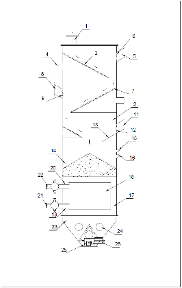
Figure 1:
Structural diagram of a urea plate cooler with dedusting function
1. Feed inlet 2. Dedusting module 3. Primary air distribution plate 4. Primary air inlet 5. Primary exhaust outlet 6. Primary powder-filtering grid 7. Secondary air distribution plate 8. Secondary exhaust outlet 9. Secondary powder-filtering grid 10. Tertiary air distribution plate 11. Tertiary exhaust outlet 12. Tertiary powder-filtering grid 13. Material retaining plate 14. Feed bin 15. Level gauge interface 16. Feed temperature gauge interface 17. Heat-transfer plate assembly 18. Heat-transfer plate 19. Heat-transfer plate water inlet 20. Heat-transfer plate water outlet 21. Main water inlet pipe 22. Main water outlet pipe 23. Discharger 24. Inspection hole 25. Positioner 26. Actuator.
4. Performance and Characteristics of the Urea Plate Cooler with Dedusting Function
(1) More than 60% energy savings compared with a fluidized-bed cooler: Compared with a traditional air-cooled fluidized-bed cooler, which uses high-power blowers and induced draft fans and therefore consumes very high amounts of energy, the urea plate cooler with dedusting function adopts water-cooling technology. The dry air used in the upper dedusting module serves only for dust removal. The installed motor power of the equipment body is usually only about 30–40% of that of a fluidized-bed cooler.
(2) Highly efficient cooling performance: In the urea plate cooler with dedusting function, urea flows by gravity through the channels between the heat-transfer plates. The residence time can be precisely controlled, enabling thorough cooling of urea granules and cooling them through to the core, thereby achieving better finished-product quality. By contrast, traditional fluidized-bed heat exchangers use air cooling, which may only cool the surface of solid particles. Packaged products may still experience temperature rebound, leading to product quality incidents.
(3) Stable moisture content of solid products: Traditional fluidized-bed coolers use air cooling. During high ambient humidity conditions, cooling air can affect the moisture content of urea granule products. Because the urea plate cooler with dedusting function uses indirect heat exchange with cooling water, it completely eliminates the risk of increasing the moisture content of finished urea granules or causing contamination. The amount of dry air used for dedusting is small, and the dry air is treated for oil and moisture removal, so it has no adverse impact on the quality of finished urea granules.
5. Conclusion
Compared with a traditional urea plate cooler, the improved urea plate cooler with dedusting function adds a high-efficiency dedusting module, thereby providing dust-removal capability and eliminating the traditional plate cooler’s weakness of insufficient dedusting. This ensures that the final product quality of solid particles is not affected by excessive powder content. Considering overall energy consumption, operating cost, maintenance cost, cooling performance, and dedusting performance, the urea plate cooler with dedusting function is superior to traditional fluidized-bed cooler and rotary-drum cooler technologies. It has become an important option for urea manufacturers seeking to eliminate dust and high-temperature caking problems.